

Products
Top View
- No recommended products available at the moment.
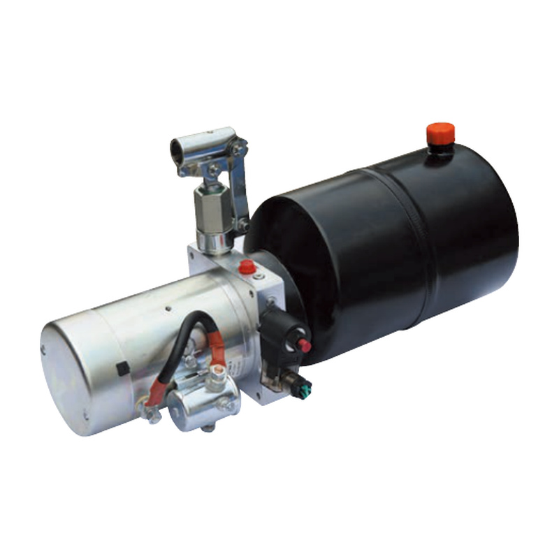
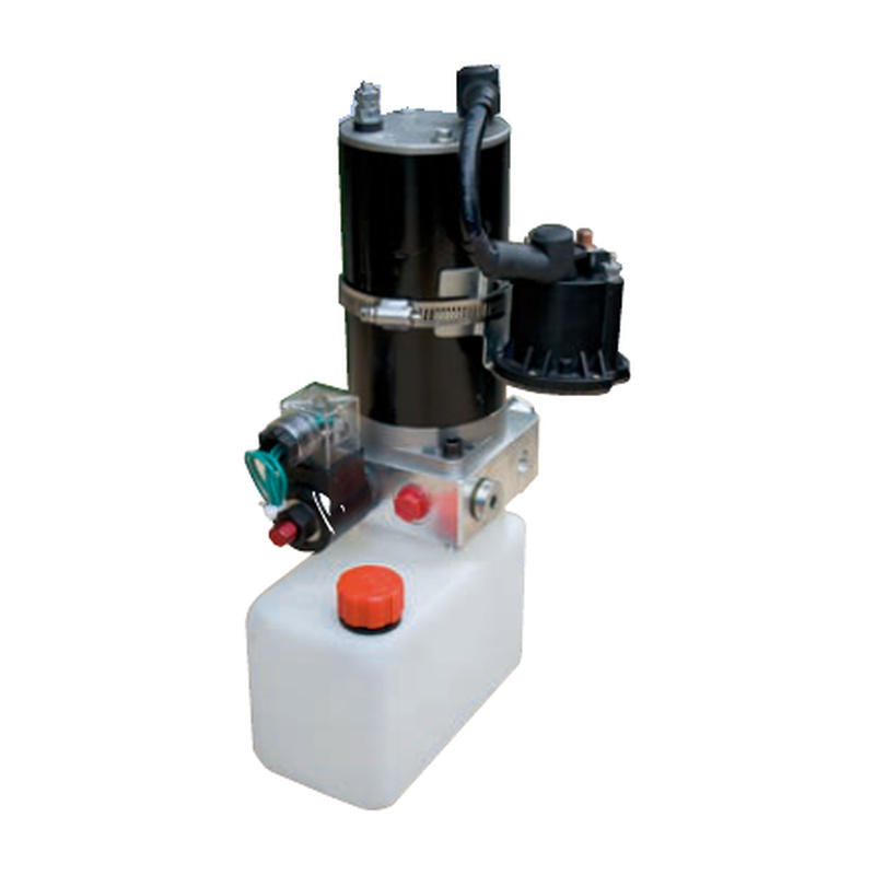
Dump Trailer Power Unit
12VDC and 24VDC hydraulic power units for dump trailers, with powered lifting and gravity lowering. The catalog includes a hand-pump backup version and a remote-control version.
Service Online:
- Overview
Hand-Pump Backup Version
Introduction
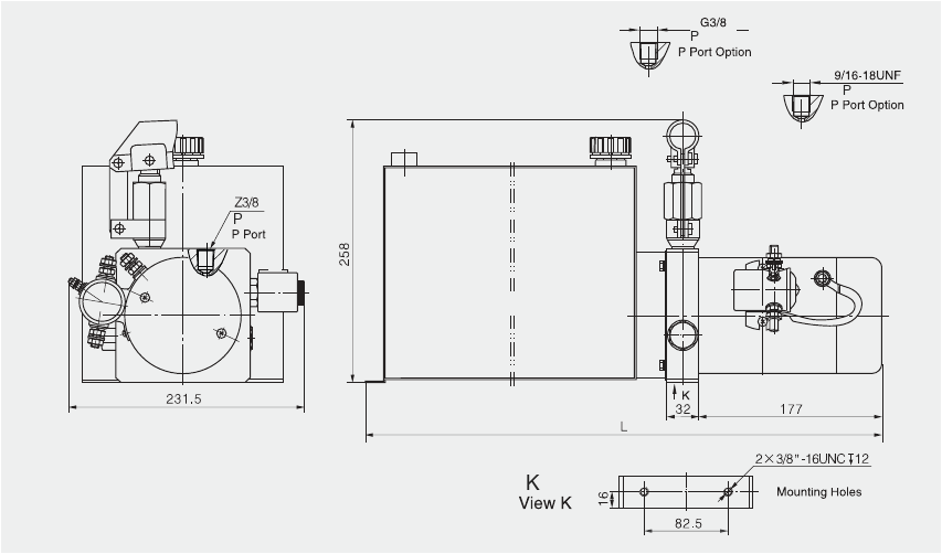
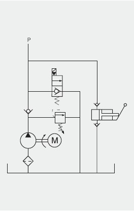
Designed for small tipping trailers, this power unit integrates a high-pressure gear pump, DC motor, multifunctional manifold, valves and tank. A hand pump with a displacement of 8 cc per stroke provides backup lifting in the event of a power failure. Lowering is activated by the solenoid valve.
External Dimension Drawing
Working Principle
Model and Specifications
| Model | Motor Voltage | Motor Power (kW) | Rated Speed (rpm) | Pump Displacement (ml/rev) | System Pressure (MPa) | Tank Capacity (L) | Solenoid Valve Voltage | L (mm) |
|---|---|---|---|---|---|---|---|---|
| YBZ5-F2.1E1W27/WUCAT1 | 12VDC | 1.5 | 2500 | 2.1 | 20 | 12 | 12VDC | 559 |
| YBZ5-F2.1H1W27/WUCAT1 | 12VDC | 1.5 | 2500 | 2.1 | 20 | 20 | 12VDC | 791 |
| YBZ5-F2.5E2A27/WUCBT1 | 24VDC | 2 | 2500 | 2.5 | 18 | 12 | 24VDC | 559 |
| YBZ5-F2.7H2A27/WUCBT1 | 24VDC | 2 | 2500 | 2.7 | 18 | 20 | 24VDC | 791 |
Remote-Control Version
Introduction
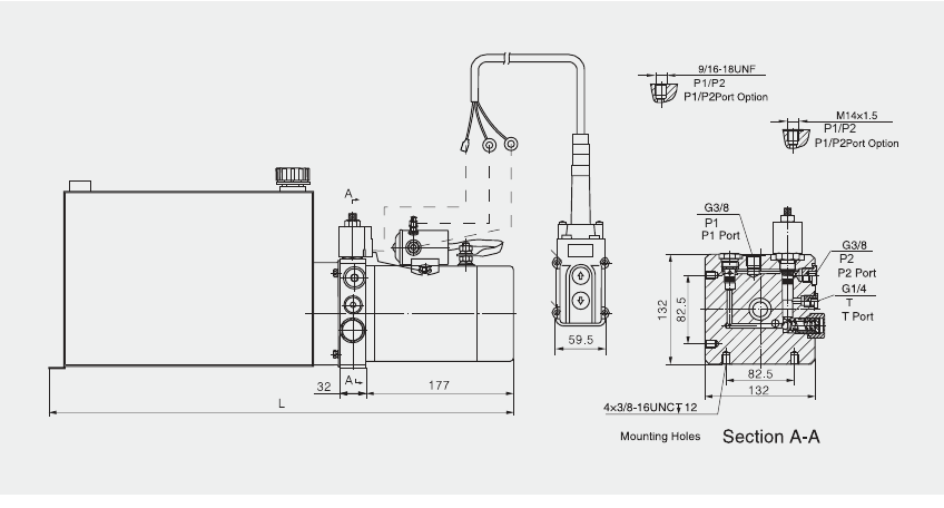
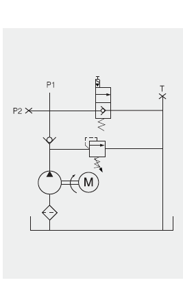
This power unit integrates a high-pressure gear pump, DC motor, multifunctional manifold, valves and tank in a power-up, gravity-down circuit. Starting the motor raises the equipment. Lowering is activated by the solenoid valve, with speed regulated by the pressure-compensated flow control valve. This series is suitable for automotive equipment, garden machinery and other material-handling applications.
External Dimension Drawing
Working Principle
Model and Specifications
| Model | Motor Voltage | Motor Power (kW) | Rated Speed (rpm) | Pump Displacement (ml/rev) | System Pressure (MPa) | Tank Capacity (L) | Solenoid Valve Voltage | L (mm) |
|---|---|---|---|---|---|---|---|---|
| YBZ5-F2.1E1W2/WUCAD1/RC | 12VDC | 1.5 | 2500 | 2.1 | 20 | 12 | 12VDC | 559 |
| YBZ5-F2.5H1W2/WUCAD1/RC | 12VDC | 1.5 | 2500 | 2.5 | 20 | 20 | 12VDC | 791 |
| YBZ5-F2.5E2A2/WUCBD1/RC | 24VDC | 2 | 2500 | 2.5 | 18 | 12 | 24VDC | 559 |
| YBZ5-F2.7G2A2/WUABD1/RC | 24VDC | 2 | 2500 | 2.7 | 18 | 16 | 24VDC | 676 |
Remarks
- Contact our sales engineer for other pump displacements, motor powers, pressures or tank capacities.
- A manual override function is available on request.
Precautions
- S3 intermittent duty: 30 seconds on and 270 seconds off. Continuous operation is not permitted.
- Clean all hydraulic components, cylinders, hoses and fittings before installing the power unit.
- Use clean hydraulic oil free of impurities, with a viscosity of 15-68 cSt. N46 hydraulic oil is recommended.
- Mount the power unit horizontally.
- Check the oil level in the tank after the initial operation of the power unit.
- Change the hydraulic oil after the first 100 operating hours and every 3,000 hours thereafter.
Related Products You May Like
PRODUCT INQUIRY
 Home
 About Us
 Products
 Tel
